Mostrando entradas con la etiqueta C. Mostrar todas las entradas

miércoles, 8 de enero de 2014

How to start creating and programming robots


Introduction


Create robots requires a lot of different skills and, depending on how sophisticated is the behavior or the tasks that must be performed, can be really complex and extremely difficult.

The three pillars of robotics are electronics, mechanics and programming; there are others, but only with these three you can already start experimenting.

In addition to applicable knowledge you also need some others items such as motors (or other actuators), sensors, a small computer to avoid weight and power consumption (typically a SBC or microcontroller ) and a power source (battery to be autonomous) and some parts that sustain and hold together all these elements and their movements.

These elements can be acquired (some even manufactured) separately, or more easily, and probably cheaper as a kit.

.

What do I need to start?


Mainly, you need wish to enjoy creating and learning.

* Acquire a minimum and basic knowledge of:

+ Electronics or electricity (if only to distinguish voltage and current),

+ Mechanics (the minimum would be screwing and unscrewing or connect Lego type pieces)

+ Computer (at least to run a program on a computer)

* Get at least a microcontroller (Arduino, for example), a pair of motors, a distance sensor, a battery, cables, and a structure to support it. The basic set or kit.

A kit, the best option


A clear advantage of starting with a kit is that you start NOW, spending your time on where is your interest (electronic, mechanical or computer) , because the others areas are already solved, but anytime you can get to work in any of them. When you buy the kit with all the necessary set of elements together, the price is also often cheaper.

From the more expensive and complex to the cheapest and easiest

bioloid_bio_img01Bioloid : 18 powerful servo motors, 4 sensors. Ideal for humanoid, quadrupeds, hexapods and even vehicles; software to create them and behave like living beings. Includes programming software RoboPlus Tasks, you can also program in C, and create motion sequences with RoboPlus Motion.  Using other controller, like Raspberry Pi you can use any language and programming tools which generate code to it.

It costs about 1000 euros. Yes, it is somewhat expensive, but if you have enough money and programming skills or willingness to learn, I think it deserves the price.

Mindstorms_EV3Mindstorm EV3: 2 servo motors, 1 motor, 4 sensors. Ideal for mechanisms and vehicles. Very easy to use, but it also allows you to create complex robots. Includes programming software NXT-G, NXT is also possible to program in Java with Far and C / C + + with Osek, not yet available for EV3 or very early versions.

It costs about 300 euros, although it may seem expensive compared to other options, its enormous potential and flexibility in all aspects (construction, programming and electronics) make it tremendously interesting.

Mindstorms EV3 is the latest version, released in August 2013.

[caption id="attachment_2226" align="alignleft" width="240"]Arduino robot Robot Arduino[/caption]

Vehicle based on Arduino: at least 2 servomotors and all the sensors  you want to start. Is easy and cheap, for about 40€/50$ - 70€/97$ you can have the a robot. Ideal for deepening in electronics.

It can be programmed with the friendly Arduino programming environment .

Is the cheapest option and you can go further by buying more components as you go. It not offers as much flexibility and ability to build as Mindstorms vehicles or Bioloid articulated robots, but you can really learn a lot more than it may seem.

.

.

.

And with less money or no money?


For less money, for starters, you can get an Arduino microcontroller or its clones, which cost just over 20 euros/dollars.

Or, completely free of charge, you can start learning to program in C or C + +, which will come very handy to program robots.

Free resources for learning C programming:

C introduction (pdf)

But there are a lot…

C Language Tutorial (html)
How C Programming Works (html)
Several C programming tutorials (html)
... and more from Google


And here you can find free resources for learning C++ programming.

In the next post I will write about a fast comparative between Bioloid, Mindstorms and Arduino based robots and about Arduino programming.

miércoles, 20 de noviembre de 2013

(I) Reading sensors connected to Robotis CM-510

cm-510 sensorsUsing the Dynamixel SDK instead of RoboPlus Tasks is not possible to query sensors connected to the CM-5xx controller. But, of course, using standard programming languages, like C++, and tools, line QT Creator or Eclipse, with its full featured IDEs and debuggers is a hugue gain.

So I created a firmware for the CM-510 which can be queried and receive commands to itself, including its sensors, or to Dynamyxel devices.

The idea is very simple:

This program running in the CM-510 receives:

- commands or queries to IDs of Dynamixel devices. These are not processed, only redirected to the Dynamixel bus only if it was received by serial port ( serial cable or zigbee). If it was received from the Dynamixel bus nothing is done.

- commands or queries to the CM-510 ID (I chose ID=200), like beep, or to the sensors connected to it. This commands and queries are processed in the CM-510, basically querying the sensors.

In both cases the answer is sent to the connection from which the query or command was received.

After power on the CM-510, you can select the mode with the 4 cursor keys as showed in a terminal connected to its serial port:

"For 'Toss mode' press (Up), for 'Device mode' (Down), for 'Device debug mode' (Left),to start press (Right)"

In the Device mode:

all the receptions and sends are through the Dynamixel bus, the CM-510 is simply another device.

In the Toss mode:

- what is received from the serial connection is sent to the Dynamixel bus or processed in the CM-510 (If sent to its ID)

-what is received from the Dynamixel bus is sent to the serial connection

Finally, the Debug mode:

is like the Device mode, but all the debug messages included in the CM-510 are sent to the serial connection.

A complete sequence with code snippets from the CM-510 program and from the code running in the other computer:

Some C++ code snippets from this example: (C# in the next post)


[sourcecode language="cpp"]
enum AX12Address //and functions implemented in the CM-510 program, like
{
ReadCM510SensorRaw = 1,
Beep = 8,
ReadCM510SensorFiltered = 4,
SetSensorValuesToFilter = 5,
...
}
[/sourcecode]

[sourcecode language="cpp"]
void doBeep()
{
cout << "Beep" << endl;
mySystem.dynamixelCommunication.sendOrder(100, AXS1_Buzzer, (byte) DO, (short) 500);
usleep (200000);
mySystem.dynamixelCommunication.sendOrder(200,MyCommunications::Beep short)5);
}
[/sourcecode]

Querying sensor:

[sourcecode language="cpp"]
void doQuerySensor()
{
int sensorPort=getSensorPort();
int value=mySystem.dynamixelCommunication.readSensorValue (200,ReadCM510SensorRaw, sensorPort);
cout << "the sensor reads: [" << value << "] " << endl << endl << endl;
}
[/sourcecode]

These command and query are processed in the CM-510:

Getting the sensor value:

[sourcecode language="c"]

int executeCM510Function()
{
...
case F_GET_SENSOR_VALUE_RAW:
values[1] = getSensorValueRaw(parameters[1]);
break;

case F_GET_SENSOR_VALUE_FILTERED:
values[1] = getSensorValueFiltered(parameters[1], sensorValuesToFilterDefined);
break;

case F_GET_TWO_DMS_SENSOR_VALUES:
parametersReceived=3;
getTwoDMSSensorsValues();
break;

case F_GET_MULTIPLE_SENSOR_VALUE:
getMultipleSensorsValues();
break;

case F_DO_SENSOR_SCAN:
values[1]= sensorScan(parameters[1]);
break;

case F_SET_VALUE_DMS1 : //set default value DMS1
DMS1=parameters[1];
break;

case F_SET_VALUE_DMS2 : //set default value DMS1
DMS2=parameters[1];
break;

case F_BEEP:
if (debugMode)
printf("executeCM510Function beep\n");
beep();
break;

case F_SET_SENSOR_VALUES_TO_FILTER:
sensorValuesToFilterDefined=parameters[1];
break;
}

return function;
}

}
...
int getSensorValueRaw(unsigned char portId)
{
ADCSRA = (1 << ADEN) | (1 << ADPS2) | (1 << ADPS1);

setPort(portId);
//PORTA &= ~0x80;
//PORTA &= ~0x20;

//_delay_us(12); // Short Delay for rising sensor signal
_delay_us(24);
ADCSRA |= (1 << ADIF); // AD-Conversion Interrupt Flag Clear
ADCSRA |= (1 << ADSC); // AD-Conversion Start

while( !(ADCSRA & (1 << ADIF)) ); // Wait until AD-Conversion complete

PORTA = 0xFC; // IR-LED Off

//printf( "%d\r\n", ADC); // Print Value on USART

//_delay_ms(50);
_delay_ms(ReadSensorDelayMS);

return ADC;
}

[/sourcecode]


[sourcecode language="c"]

void beep()
{
buzzOn(100);
buzzOff();
}
[/sourcecode]

But we can do a little more with the CM-510 processor, we can do some filtering to the sensor values.

The readings from the DMS are usually somewhat erratic, so we can simply:

- discard the minimum and maximum values:

- if we take 5 more than measures, then return the average if the are more than 3, if 3 or less it

Previously we should set how many readings should be done, if not, the default number of readings are 5:

[sourcecode language="c"]
int getSensorValueFiltered(unsigned char portId, int times)
{
...
switch(function)
{
case F_GET_SENSOR_VALUE_RAW:
values[1] = getSensorValueRaw(parameters[1]);
break;

case F_GET_SENSOR_VALUE_FILTERED:
values[1] = getSensorValueFiltered(parameters[1], sensorValuesToFilterDefined);
break;

case F_GET_TWO_DMS_SENSOR_VALUES:
parametersReceived=3;
getTwoDMSSensorsValues();
break;

case F_GET_MULTIPLE_SENSOR_VALUE:
getMultipleSensorsValues();
break;

case F_DO_SENSOR_SCAN:
values[1]= sensorScan(parameters[1]);
break;

case F_SET_VALUE_DMS1 : //set default value DMS1
DMS1=parameters[1];
break;

case F_SET_VALUE_DMS2 : //set default value DMS1
DMS2=parameters[1];
break;

case F_BEEP:
if (debugMode)
printf("executeCM510Function beep\n");
beep();
break;

case F_SET_SENSOR_VALUES_TO_FILTER:
sensorValuesToFilterDefined=parameters[1];
break;
}
...
[/sourcecode]

We also can take values from multiple sensors with one query, but It will be explained in the next post...

lunes, 29 de julio de 2013

(I) Programming serial port communications

250px-Serial_portConnections and operating system symbolic names

A serial port is a communication physical interface through which information  transfers in or out one bit at a time (in contrast to a parallel port) being, more or less compliant, with the RS-232 standard.

But serial port communications aren't only useful for wired DE-9 connectors. it also allows us to use it with USB (ftdi), Bluetooth (serial profile) and Zigbee using virtual serial ports.

·

Types-usbSerial and virtual serial ports appear as  COMx in Windows operating systems (COM1, COM2, ...) andin UNIX/Linux as ttySx or ttyUSBx or even ttyACMx (ttyS0, ttyS1, ttyUSB0, ttyUSB1, ttyACM0, ttyACM1,...).

For programming purposes we usually want to communicate computers with others computers, microcontrollers or other devices like GPS, LED or LCD displays.

·

Serial port programming in C/C++, Windows and Linux

Using the serial port is a lot  easier, but sometimes tricky. The basic commands are to open a connection, read and write over this connection and, finally, tom close it, better if using the C++ RAII idiom.

winWindows commands:
Here you can find a complete C++ for Windows example.

With these next two definitions (among others needed):

HANDLE
serialPortHandle
wchar_t* device

serialPortHandle = CreateFile(device, GENERIC_READ | GENERIC_WRITE, 0, NULL, OPEN_EXISTING, NULL, NULL);


if (serialPortHandle!=INVALID_HANDLE_VALUE)
ReadFile(serialPortHandle, buffer, len, &read_nbr, NULL);

...
if (serialPortHandle!=INVALID_HANDLE_VALUE)
WriteFile(serialPortHandle, buffer, len, &result, NULL);


CloseHandle(serialPortHandle);

linuxUnix/Linux commands:
Here you can find a complete C++ for Linux example.

With these two definitions:
·

int fileDescriptor;

char *device;


·

·


  • Opening a connection, open


struct termios terminalAttributes;

fileDescriptor = open(device, O_RDWR | O_NOCTTY | O_NDELAY | O_FSYNC );

// clear terminalAttributes data
memset(&terminalAttributes, 0, sizeof(struct termios));

terminalAttributes.c_cflag = B57600 | CS8 | CLOCAL | CREAD;
terminalAttributes.c_iflag = IGNPAR |  ONLCR;
terminalAttributes.c_oflag = OPOST;
terminalAttributes.c_cc[VTIME] = 0;
terminalAttributes.c_cc[VMIN] = 1;

tcsetattr(fileDescriptor, TCSANOW, &terminalAttributes);


int n=read(fileDescriptor, buffer, len);

...
int n=write(fileDescriptor, buffer, len);


  • Closing the connection, close


close(fileDescriptor);

More information:


https://en.wikipedia.org/wiki/Serial_communication
http://en.wikipedia.org/wiki/Serial_port

http://www.lvr.com/serport.htm
http://digilander.libero.it/robang/rubrica/serial.htm
http://en.wikibooks.org/wiki/Serial_Programming

http://msdn.microsoft.com/en-us/library/ff802693.aspx

domingo, 16 de junio de 2013

Arduino LCD 1602 (16x2) display

Another little pearl from www.dx.com is the Arduino compatible LCD 1602 (16 characters each of the 2 rows) display:

20130616_091530

It's really cheap, 6$/4.5€, works very fine and it's easy to use! I will use as a handy debug display and little dashboard (it has 6 buttons at the bottom) while on field robots debugging, but this wioll be a near post with the sourcecode (that also will be a order receiver to program a Rapsberry Pi to control a robot using and Arduino Funduino Duemilanove.)

Arduino LCD text

Two easy examples from the Arduino IDE wondeful examples, it's important that you notice that the initialization sentence should be:

LiquidCrystal lcd(8, 9, 4, 5, 6, 7);

The hello world
[sourcecode language="C"]
/*
LiquidCrystal Library - Hello World

Demonstrates the use a 16x2 LCD display. The LiquidCrystal
library works with all LCD displays that are compatible with the
Hitachi HD44780 driver. There are many of them out there, and you
can usually tell them by the 16-pin interface.

This sketch prints "Hello World!" to the LCD
and shows the time.

The circuit:
* LCD RS pin to digital pin 12
* LCD Enable pin to digital pin 11
* LCD D4 pin to digital pin 5
* LCD D5 pin to digital pin 4
* LCD D6 pin to digital pin 3
* LCD D7 pin to digital pin 2
* LCD R/W pin to ground
* 10K resistor:
* ends to +5V and ground
* wiper to LCD VO pin (pin 3)

Library originally added 18 Apr 2008
by David A. Mellis
library modified 5 Jul 2009
by Limor Fried (http://www.ladyada.net)
example added 9 Jul 2009
by Tom Igoe
modified 22 Nov 2010
by Tom Igoe

This example code is in the public domain.

http://www.arduino.cc/en/Tutorial/LiquidCrystal
*/

// include the library code:
#include <LiquidCrystal.h>

// initialize the library with the numbers of the interface pins
//LiquidCrystal lcd(12, 11, 5, 4, 3, 2);
LiquidCrystal lcd(8, 9, 4, 5, 6, 7);

void setup() {
// set up the LCD's number of columns and rows:
lcd.begin(16, 2);
// Print a message to the LCD.
lcd.print("Te, amo, Nuriitaa!");
}

void loop() {
// set the cursor to column 0, line 1
// (note: line 1 is the second row, since counting begins with 0):
lcd.setCursor(0, 1);
// print the number of seconds since reset:
lcd.print(millis()/1000);
}
[/sourcecode]

Testing buttons
[sourcecode language="C"]
//Sample using LiquidCrystal library
#include <LiquidCrystal.h>

/*******************************************************

This program will test the LCD panel and the buttons
Mark Bramwell, July 2010

********************************************************/

// select the pins used on the LCD panel
LiquidCrystal lcd(8, 9, 4, 5, 6, 7);

// define some values used by the panel and buttons
int lcd_key = 0;
int adc_key_in = 0;
#define btnRIGHT 0
#define btnUP 1
#define btnDOWN 2
#define btnLEFT 3
#define btnSELECT 4
#define btnNONE 5

// read the buttons
int read_LCD_buttons()
{
adc_key_in = analogRead(0); // read the value from the sensor
// my buttons when read are centered at these valies: 0, 144, 329, 504, 741
// we add approx 50 to those values and check to see if we are close
if (adc_key_in > 1000) return btnNONE; // We make this the 1st option for speed reasons since it will be the most likely result
if (adc_key_in < 50) return btnRIGHT;
if (adc_key_in < 195) return btnUP;
if (adc_key_in < 380) return btnDOWN;
if (adc_key_in < 555) return btnLEFT;
if (adc_key_in < 790) return btnSELECT;
return btnNONE; // when all others fail, return this...
}

void setup()
{
lcd.begin(16, 2); // start the library
lcd.setCursor(0,0);
lcd.print("Push the buttons"); // print a simple message
}

void loop()
{
lcd.setCursor(9,1); // move cursor to second line "1" and 9 spaces over
lcd.print(millis()/1000); // display seconds elapsed since power-up


lcd.setCursor(0,1); // move to the begining of the second line
lcd_key = read_LCD_buttons(); // read the buttons

switch (lcd_key) // depending on which button was pushed, we perform an action
{
case btnRIGHT:
{
lcd.print("RIGHT ");
break;
}
case btnLEFT:
{
lcd.print("LEFT ");
break;
}
case btnUP:
{
lcd.print("UP ");
break;
}
case btnDOWN:
{
lcd.print("DOWN ");
break;
}
case btnSELECT:
{
lcd.print("SELECT");
break;
}
case btnNONE:
{
lcd.print("NONE ");
break;
}
}
}
[/sourcecode]

miércoles, 12 de junio de 2013

Robotis CM-900 as a tosser for Dynamixel commands

CM-900 is really tiny and cheap, so is perfect to use as communication bridge between any computer (Raspberry Pi, Pandaboard, etc. included, of course) and the Dynamixel bus. Whatever it receives from the Serial USB (usually commands and queries) is sent to the Dynamixel bus, and what it receives from the Dynamixel bus is sent to the SerialUSB (usually answers)

Here is the source code of the little program for CM-900 IDE:

[sourcecode language="C"]
int counter;
bool onlyOnceHappened;

void blinkOnce()
{
digitalWrite(BOARD_LED_PIN, LOW);
delay_us(100);
digitalWrite(BOARD_LED_PIN, HIGH);
}

void setup()
{
pinMode(BOARD_LED_PIN, OUTPUT);

onlyOnceHappened=false;
counter=0;

//USB Serial initialize
SerialUSB.begin();
// SerialUSB.attachInterrupt(USBDataReceived);
//DXL initialize
Dxl.begin(1);
}

byte aByte=0;
uint8 aUint8;

void loop()
{
// SerialUSB.println (counter++);

if (onlyOnceHappened==false)
{
blinkOnce();
onlyOnceHappened=true;
delay (3000); //Some time to the user to activate the monitor/console
SerialUSB.println ("v1.1.1 Orders receiver started");
}

if (SerialUSB.available())
{
aUint8=SerialUSB.read();
blinkOnce();
Dxl.writeRaw(aUint8);
// delay(20);
}

if (Dxl.available())
{
aByte=Dxl.readRaw();
blinkOnce();
SerialUSB.write(aByte);
// delay(20);
}
}

[/sourcecode]

Here the file.

In the next post I will include an improved version that could read sensors connected to the CM-900, "expanding" the Dynamixel protocol.

lunes, 15 de abril de 2013

Cheapest Smart Car Robot: parts, examples of use and documentation

[caption id="attachment_1552" align="aligncenter" width="600"]Ultrasonic Smart Car Kit Ultrasonic Smart Car Kit[/caption]

[caption id="attachment_1746" align="alignleft" width="150"]Funduino Arduino DuemilaNove clon Funduino Arduino DuemilaNove clon[/caption]

It's really cheap but it does not include any documentation; but don't panic, all you will need can be found on Internet. And now, the main electronic components: the microcontroller, the dual motor driver, the ultrasonic sensor and the servo:

The microcontroller brain is a Funduino (Arduino Duemilanove clone), and as far I've used it (and as other buyer said is fully, at least for software, compatible). Here we will not have any problem because there are a lot of documentation about Arduino and Duemilanove.

A simple hello world example (here the file)

[sourcecode language="c"]

// Blinking LED

int ledPin = 13;                 // LED connected to digital pin 13

void setup()
{
Serial.begin(57600);
printf (&amp;amp;quot;Setup/n/l&amp;amp;quot;);
Serial.println(&amp;amp;quot;Hello world!&amp;amp;quot;);
pinMode(ledPin, OUTPUT);      // sets the digital pin as output
}

void loop()
{
printf (&amp;amp;quot;2009&amp;amp;quot;);
Serial.println(&amp;amp;quot;2009&amp;amp;quot;);
digitalWrite(ledPin, HIGH);   // sets the LED on
delay(1000);                  // waits for a second
digitalWrite(ledPin, LOW);    // sets the LED off
delay(1000);                  // waits for a second
}

[/sourcecode]

[caption id="attachment_1748" align="alignleft" width="150"]Dual_H-Bridge_Motor_Driver Dual_H-Bridge_Motor_Driver[/caption]

But to control the two motors this kit use an Dual H-Bridge motor driver (L298). Here (read the Drive Two DC Motors section) you can find a lot of useful documentation and examples,  and  here you can find also more information, specially about electronics.

Here the file with the example

[sourcecode language="c"]
int ENA=5;//connected to Arduino's port 5(output pwm)
int IN1=2;//connected to Arduino's port 2
int IN2=3;//connected to Arduino's port 3
int ENB=6;//connected to Arduino's port 6(output pwm)
int IN3=4;//connected to Arduino's port 4
int IN4=7;//connected to Arduino's port 7
void setup()
{
Serial.begin(57600);
Serial.println(&amp;amp;quot;Two motors&amp;amp;quot;);
pinMode(ENA,OUTPUT);//output
pinMode(ENB,OUTPUT);
pinMode(IN1,OUTPUT);
pinMode(IN2,OUTPUT);
pinMode(IN3,OUTPUT);
pinMode(IN4,OUTPUT);
digitalWrite(ENA,LOW);
digitalWrite(ENB,LOW);//stop driving
digitalWrite(IN1,LOW);
digitalWrite(IN2,HIGH);//setting motorA's directon
digitalWrite(IN3,HIGH);
digitalWrite(IN4,LOW);//setting motorB's directon
}
void loop()
{
analogWrite(ENA,255);//start driving motorA
analogWrite(ENB,255);//start driving motorB
delay(3000);
analogWrite (IN1,0);//stop driving motorA
analogWrite (IN2,0);//stop driving motorB

analogWrite (IN3,0);//stop driving motorA
analogWrite (IN4,0);//stop driving motorB

delay (3000);

int ledPin = 13;
while (1)
{
digitalWrite(ledPin, HIGH);   // sets the LED on
delay(1000);                  // waits for a second
digitalWrite(ledPin, LOW);    // sets the LED off
delay(000);
}
&amp;amp;lt;pre&amp;amp;gt;[/sourcecode]

[caption id="attachment_1753" align="alignleft" width="150"]Ultrasonic sensor hc-sr04 Ultrasonic sensor hc-sr04[/caption]

The HC-SR04 ultrasonic distance sensor, example of use (here the file):

[sourcecode language="c"]

#define trigPin 9
#define echoPin 11

void setup() {
Serial.begin (115200);
pinMode(trigPin, OUTPUT);
pinMode(echoPin, INPUT);
}

void loop() {
int duration, distance;
digitalWrite(trigPin, HIGH);
delayMicroseconds(1000);
digitalWrite(trigPin, LOW);
duration = pulseIn(echoPin, HIGH);
distance = (duration/2) / 29.1;
if (distance &amp;amp;gt; 400 || distance &amp;amp;lt; 0){
Serial.println(&amp;amp;quot;Out of range&amp;amp;quot;);
}
else {
Serial.print(distance);
Serial.println(&amp;amp;quot; cm&amp;amp;quot;);
}
delay(500);
}

[/sourcecode]


[caption id="attachment_1755" align="alignleft" width="150"]TowerPro micro servo SG90 TowerPro micro servo SG90[/caption]

And the Tower PRO SG-90 micro servo (and here the file with the example):

[sourcecode language="c"]
// Sweep
// by BARRAGAN &amp;amp;lt;http://barraganstudio.com&amp;amp;gt;
// This example code is in the public domain.

#include &amp;amp;lt;Servo.h&amp;amp;gt;

Servo myservo;  // create servo object to control a servo
// a maximum of eight servo objects can be created

int pos = 0;    // variable to store the servo position

void setup()
{
myservo.attach(3);  // attaches the servo on pin 3 to the servo object
}

void loop()
{
for(pos = 0; pos &amp;amp;lt; 180; pos += 1)  // goes from 0 degrees to 180 degrees
{                                  // in steps of 1 degree
myservo.write(pos);              // tell servo to go to position in variable 'pos'
delay(15);                       // waits 15ms for the servo to reach the position
}
for(pos = 180; pos&amp;amp;gt;=1; pos-=1)     // goes from 180 degrees to 0 degrees
{
myservo.write(pos);              // tell servo to go to position in variable 'pos'
delay(15);                       // waits 15ms for the servo to reach the position
}
}
[/sourcecode]

Soon I will add an LCD display with 6 buttons

CM-900 Robotis IDE more programming examples

I've started to program CM-900 "translating" the example from the C programming tutorial for CM-510

CM900_with_its parts_names

You can get more information at robotsource.org CM-900 community circle and the CM-900 e-manual. There you can find:

- Quick start guide

- Presentation Workshop

- Arduino based IDE to program it very easily (examples included)

- Source code and instructions

- Using other servos

- Interfacing sensors

I already have "translated" two examples: a simple "hello world" like where a servo is move to 2 different positions and another where the servo id and position is asked and after entered the data the servo is positionated in the typed position, validating that id and position are in range.

The "hello World " example (here the zipped file):

[sourcecode language="c"]
#define P_GOAL_POSITION_L     30
#define P_MOVING              46

int counter;
int onlyOnceHappened;

void setup()
{
//USB Serial initialize

onlyOnceHappened=0;
counter=0;

SerialUSB.begin();
Dxl.begin(1);
delay (5000);
SerialUSB.println("Setup");
}

void loop()
{

delay (3000);
SerialUSB.print("loop");
SerialUSB.println(counter);
counter++;
delay(1000);

if (onlyOnceHappened==0)
{
onlyOnceHappened=1;
SerialUSB.println("Hello, World");
}

int id=8;

SerialUSB.println ("Simple example #0");

SerialUSB.print ("Perform movement 1 with the AX-12:");
SerialUSB.println (id);
byte bMoving = Dxl.readByte( id, P_MOVING);
byte CommStatus = Dxl.getResult();
if( CommStatus == COMM_RXSUCCESS )
Dxl.writeWord( id, P_GOAL_POSITION_L, 511 );
else
SerialUSB.println ("CommStatus IS NOT COMM_RXSUCCESS");

SerialUSB.println ("Pause half a second");
delay (500); // half-second pause

SerialUSB.println ("Beep!");
//buzzOn (100); // beep

SerialUSB.println ("Pause for a second");
delay (1000); // pause for 1 second

SerialUSB.print ("Perform movement 2 with the AX-12: ");
SerialUSB.println (id);

Dxl.writeWord( id, P_GOAL_POSITION_L, 611 );

SerialUSB.println ("End");

}
[/sourcecode]

Asking Id and Position example, (here the zipped file)

[sourcecode language="c"]

int counter;
bool onlyOnceHappened;

int id;
int position;

bool debugOutputOn;
char charReaded;

void debugOutputUSB(char *buffer, bool newlineAfterMessage)
{
if (debugOutputOn)
{
if (newlineAfterMessage)
SerialUSB.println(buffer);
else
SerialUSB.print(buffer);
}
}

void debugOutputUSB(int value, bool newlineAfterMessage)
{
if (debugOutputOn)
{
if (newlineAfterMessage)
SerialUSB.println(value);
else
SerialUSB.print(value);
}
}

void debugOutputPairUSB(char *buffer, int value)
{
if (debugOutputOn)
{
SerialUSB.println ("");
SerialUSB.print(buffer);
SerialUSB.println(value);
}
}

void debugOutputPairUSB(char *buffer1, char *buffer2)
{
if (debugOutputOn)
{
SerialUSB.println ("");
SerialUSB.print(buffer1);
SerialUSB.println(buffer2);
}
}

void setup()
{
//USB Serial initialize

onlyOnceHappened=false;
counter=0;
debugOutputOn=false;

SerialUSB.begin();
Dxl.begin(1);
delay (3000);

debugOutputUSB("Setuped", true);
}

void checkIfDebugOn()
{
SerialUSB.print("Put debug ON?, y/n");
charReaded=SerialUSB.read();

if (charReaded=='y' || charReaded=='Y')
debugOutputOn=true;
else
debugOutputOn=false;

debugOutputPairUSB ("DebugPut is:", debugOutputOn);
}

void loop()
{
delay (1500);
SerialUSB.println ("Simple example #1");

if (onlyOnceHappened==false)
{
onlyOnceHappened=true;
checkIfDebugOn();
}

debugOutputPairUSB  ("Loop: ",counter);
counter++;
delay(500);

debugOutputUSB("Starting loop", true);

while(true) // we'll repeat this loop forever
{
id=getId(); // get the ID of the AX-12 that we want to move
position=getPosition(); // get the goal position

Dxl.writeWord( id, P_GOAL_POSITION_L, position); // sent the command to the Dynamixel
debugOutputUSB ("Dxl.writeWorded", true);
}
}
// I have created a simple ayoi because I have problem compiling atoi
int myatoi(char *buffer)
{
int len=strlen(buffer)-2;
int value=0;
int i=0;
int base=0;
int number=0;

for (i=len;i>=0;i--)
{
number=int(buffer[i])-int('0');

debugOutputPairUSB ("buffer[i]: ", int(buffer[i]));

if (i==len)
{
value=number;
}
else
{
value+=base * number;
}

debugOutputPairUSB ("i: ",i);
debugOutputPairUSB ("number: ", number);
debugOutputPairUSB("base: ", base);
debugOutputPairUSB("valor: ", value);

if (base==0)
{
base=10;
}
else
base=base*10;
}

return value;
}

bool isValid(int value, int MinValue, int MaxValue)
{
return (value>=MinValue && value<=MaxValue);
}

void readString(char *bufferParameter)
{
int i=0; // We'll use this variable as index of the buffer where we will store data

do
{
bufferParameter[i]=(char) SerialUSB.read(); // it store the read character in the i position of bufferParameter
SerialUSB.print(bufferParameter[i]); // showing it
if (bufferParameter[i]=='\b') // if Backspace was pressed
i--; // it goes to the previous position, rewritting the previoulsy typed character
else //
i++; // it will write in the next position
//    SerialUSB.println(int(bufferParameter[i-1]));
}while(bufferParameter[i-1]!=10); // while the last values is not INTRO. The symmbol ! represents the logical operator NOT

bufferParameter[i]=0; // A NULL (0, zero) is necessary in the last position of any string
}

/*
It read an string, it's converted to integer and returned
*/
int readInteger(char *bufferParameter)
{
//  return SerialUSB.parseInt();

readString(bufferParameter);

//  int valor=int(bufferParameter[0]-int('0'));
debugOutputPairUSB ("Leido: ", bufferParameter);
int valor=myatoi(bufferParameter);

debugOutputPairUSB ("Valor leido: ", valor);

return valor;
}

int getId()
{
/*
We define an array enough large, 256 bytes (characters). Probably it's enough with 4 bytes, but if we type more than the defined size we will get an error*/
char buffer[256];

/*
And we define another integer variable, it's very advisable to asign a value in the definition, in this case we assign the minimun value, 1*/
int ax12Id=1;

do
{ // starting the loop
SerialUSB.println ("Enter the ID of the AX-12 that you wwant to move, between 1 y 18: ");
SerialUSB.print("Id:");
ax12Id=readInteger(buffer); // this function will read from what we type in the keyboard
//// exclamation (!) is the NOT logical operator. It will repeat the loop while the value is not valid
}while(!isValid(ax12Id, 1, 18));

// Showing the typed value
SerialUSB.println(" ");
SerialUSB.print("AX12 ID:");
SerialUSB.println(ax12Id);

return ax12Id;
}

int getPosition()
{
char buffer[256];
int position=0;

do
{
SerialUSB.println ("Enter a value between 0 and 1023 as the goal position");
SerialUSB.print ("Position:");
position=readInteger(buffer);
}while(!isValid(position, 0, 1023));

// Showing the typed value
SerialUSB.println(" ");
SerialUSB.print("Position:");
SerialUSB.println(position);

return position;
}

[/sourcecode]

domingo, 17 de marzo de 2013

C. C++, C# robotics programming Workshop/tutorial with the cheapest robotic platform

[caption id="" align="alignleft" width="108"]My Smart Car construction My Smart Car construction[/caption]

[Update March 30, 2013: Added photo gallery]

I will start a C. C++, C# robotics programming Workshop/tutorial with the cheapest robotic platform I have found at dealextreme.com: (Arduino based) plus a Raspberry Pi (like this that use Bioloid as the hardware platform):

Ultrasonic Smart Car Kit

I have not still received the kit, but I will review the kit and start the workshop as soon as I receive it.

lunes, 29 de octubre de 2012

Robotizando un coche teledirigido con Arduino

Esta es la primera entrega de una serie (espero) de ellas sobre cómo hackear un coche teledirigido y ponerle todos los sensores y cacharros que se nos ocurran.

Por supuesto, empezaremos por el principio: cómo hacer que el coche sea autónomo a través de un Arduino. El elegido en este caso es el Arduino Leonardo, pero vale  casi cualquier otro.

Materiales necesarios:

  • Un coche teledirigido baratillo, de los chinos mismo

  • Una placa Arduino

  • Cuatro resistencias (yo usé de 1K, pero valen de un valor +-50%)

  • Estaño

  • Funda termoretráctil

  • Varios cables de colores (a poder ser) de unos 20cm

  • Una batería de 9V


Herramientas necesarias:

  • Estañador

  • Destornillador

  • Pelacables (o una navaja, en su defecto)

  • Alicates de corte diagonal

  • Desoldador de estaño (no imprescindible, pero sí recomendable)


Pasos a seguir:

1. Desmonta el coche

Photobucket

Photobucket

Photobucket

2. Desatornilla la placa

Photobucket

3. Elimina el circuito integrado, ya que no lo necesitaremos para nada. Para ello tienes dos opciones:

a) Consigues calentar el estaño de sus patitas y lo sacas como Dios manda o...
b) Con los alicates le cortas las patitas por la parte de arriba y lo sacas con unas pinzas. Yo me he decidido por esta segunda opción. ;)

Photobucket

Éste es el aspecto que mostrará cuando las hayas cortado todas:

Photobucket

Photobucket

4. Prepara las resistencias

Lo que vamos a hacer ahora es proteger nuestra placa, por lo que vamos a coger las cuatro resistencias que tenemos (en mi caso de 1K, pero ya digo que el valor no es crítico, pueden ir desde 0,5K a 1,5K) y cuatro cables de colores de unos 10cm de largo, y los vamos a unir formando binomios resistencia-cable:

Photobucket

Cuando ya tengas las parejas hechas, consolida la unión con estaño.

Photobucket

Las cuatro parejas tendrán este aspecto:

Photobucket

Elimina el trozo sobrante con los alicates de corte.

5. Estudia el circuito integrado que desechaste

Fíjate en las letras impresas que tiene encima para poder Googlearlo. Si has comprado un coche en un chino o en algún sitio por el estilo, seguramente tendrás un integrado como este:

http://jumpjack.altervista.org/digitalrome/progetti/macchinina/TX-2C%28RX-2C%29AY.pdf

Lo que se trata es de buscar a qué corresponde cada pata del integrado para poder controlar nosotros a voluntad el coche. Fïjate que en este pdf aparecen tanto las especificaciones del transmisor (el que está en el mando), como del receptor (que es el que nos interesa). Los pines que estamos buscando son los correspondientes a:

  • Tierra (GND)

  • Derecha (RIGHT)

  • Izquierda (LEFT)

  • Marcha atrás (BACKWARD)

  • Hacia delante (FORWARD)


En mi caso, se trata de los pines 2, 6, 7, 10 y 11.

6. Introduce las parejas que preparaste y el quinto cable en los pines que has identificado

Lo que tienes que hacer ahora es, con ayuda del estañador y el desoldador, eliminar las patitas correspondientes a esos pines para poder introducir las resistencias por los agujeros. Procura limpiar bien la zona con el desoldador para que sea más fácil introducir la pata de la resistencia, aunque ya te digo que yo no tenía y no me costó excesivo trabajo dejar la zona presentable).

A continuación, introduce las cuatro resistencias por los pines correspondientes a las dos marchas y a los lados izquierdo y derecho de la siguiente manera:

Photobucket

Puedes observar que la resistencia queda hacia el lado de arriba, y cómo están limpios y preparados el resto de agujeros. Éste es el aspecto que tiene por debajo:

Photobucket

Una vez introduzcas las cuatro resistencias y el quinto cable que tenías apartado, pero aun no habías usado (es el que va en la patilla de GND, efectivamente), estaña los cinco pines y corta el sobrante tanto de las resistencias como del cable de tierra que te sobrará.

Photobucket

Photobucket

Éste es el aspecto que tendrá tu placa entonces:

Photobucket

7. Protegiendo tu placa

Lo que vas a hacer ahora es proteger esas parejas que hemos introducido con la funda termoretráctil. Para ello corta en varios trozos la funda de tal manera que cada trozo cubra totalmente la resistencia, el trozo estañado y un poco del cable. Unos 10-15 cm, vamos. Y como bien dice su nombre, aplícale calor para que se retraiga y se moldee según la resistencia y el cable. Puedes usar desde un mechero o una cerilla a un secador de pelo. Tú mismo. El objetivo es darle un mejor acabado a las conexiones eléctricas y dotar de protección mecánica y anti-abrasiva a los cables y demás componentes eléctricos.

Photobucket

Photobucket

Éste será el aspecto que tendrá finalmente tu placa.

8. Preparando el Arduino

Si no lo has hecho antes, ahora es el momento de anotar a qué color corresponde cada pin. Puedes hacer una tabla como la siguiente (la que resultó en mi caso):

PIN                  COLOR                  FUNCIÓN

2                               Verde                             GND

6                               Gris                                 Derecha

7                               Azul                                Izquierda

10                            Blanco                           Marcha atrás

11                            Amarillo                       Adelante

El código que vamos a preparar es muy sencillo, ya que únicamente se trata de verificar las cuatro funciones: las dos direcciones marcha atrás y adelante, y los dos lados izquierda y derecha. Se trata del siguiente:

[sourcecode language="c"]
/*
Probando las cuatro órdenes del coche
*/

int forward = 12;  // Forward pin
int reverse = 11;  // Reverse pin
int left = 10;     // Left pin
int right = 9;     // Right pin

void setup()       // Configuración de los pines como salidas
{
pinMode(forward, OUTPUT);
pinMode(reverse, OUTPUT);
pinMode(left, OUTPUT);
pinMode(right, OUTPUT);
}

void go_forward()
{
digitalWrite(forward,HIGH);  // Da la orden de adelante
digitalWrite(reverse,LOW);   // Apaga la orden de marcha atrás
}
void go_reverse()
{
digitalWrite(reverse,HIGH);  // Da la orden de marcha atrás
digitalWrite(forward,LOW);   // Apaga la orden de adelante
}
void stop_car()
{
digitalWrite(reverse,LOW);   // Apaga todas las órdenes
digitalWrite(forward,LOW);
digitalWrite(left,LOW);
digitalWrite(right,LOW);
}
void go_left()
{
digitalWrite(left,HIGH);     // Da la orden de izquierda
digitalWrite(right,LOW);     // Quita la orden de derecha
}
void go_right()
{
digitalWrite(right,HIGH);    // Da la orden de derecha
digitalWrite(left,LOW);      // Quita la orden de izquierda
}

void loop()
{

go_forward();
go_left();
delay(500);

stop_car();
delay(500);

go_reverse();
go_left();
delay(500);

stop_car();
delay(500);

go_forward();
go_right();
delay(500);

stop_car();
delay(500);

go_reverse();
go_right();
delay(500);

stop_car();
delay(500);

}
[/sourcecode]

9. Conectando y probando el Arduino

Y por fin llega el último paso: donde por fin pruebas si todo esto funciona. Elimina la antena del coche si no lo has hecho ya (obviamente, no nos hará falta) y atornilla la placa con los tornillos que quitaste en el paso 2.

Conecta los cables según los pines que has declarado en el programa (en mi caso del 9 al 12) y los colores que anotaste antes. El color de tierra lo llevarás al GND de la placa, que como ves en la foto, está junto a los otros cuatro cables (en mi caso, repito):

Photobucket

Para realizar las pruebas de código, o variaciones, te recomiendo que aun no alimentes la placa con una batería, de tal manera que tendrás que tener la placa accesible al USB. Puedes volver a montar el coche y sujetar la placa con una goma elástica, como en mi caso, o dejarlo ya desmontado para introducir la placa y la batería dentro. Ahí según tu elección.

10. Alimentando la placa

Tan sólo falta el toque final: hacer el coche totalmente autónomo. Con el código ya probado ya sabes que se mueve solo, así que sólo falta el tema de la alimentación. Para ello puedes usar una batería normal de 9V, como esta:

Photobucket

Puedes fijarla tanto en el propio chasis del coche (si tienes sitio), como en la carrocería (algo como esto):

Photobucket

La conexión la puedes realizar con un enchufe centro-positivo en el conector de alimentación de la placa, o con unos simples cables como los ya empleados, insertándolos en los pines GND y Vin del conector POWER de la placa. Según tengas el adaptador o no.

El resultado será algo como esto:

[youtube http://www.youtube.com/watch?v=ulftGvqm1LU]

Espero que te haya resultado divertido. Si tienes cualquier pregunta o duda, estamos aquí para ayudarte.

Un saludo y nos vemos en la siguiente entrega! :D

lunes, 7 de mayo de 2012

Programming CM-510 with C: reading values from terminal and moving a Dynamixel AX-12

Programming CM-510 with C: reading values from terminal and moving a Dynamixel AX-12

In this post we are going to ask the ID AX-12+ that we want to move and the goal position.

The explanations are in the code as comments, I hope that there are enough comments to understand it, let me know if you can't understand it.

The main loop is that easy:

[sourcecode language="c"]
int main(void)
{
init();

while(true) // we'll repeat this looop forever
{
int id=getId(); // get the ID of the AX-12 that we want to move
int position=getPosition(); // get the goal position
dxl_write_word( id, P_GOAL_POSITION_L, position); // sent the command to the Dynamixel
}

return 0;
}
[/sourcecode]

A brief explanation of printf: printf function is much more powerful than it seems at a first sight, it admits many parameters that allow us to display a large amount of data types and formats. In In the following example %i means that in that position the message will include an integer that will be passed as a parameter after the string "AX12 ID:". The control character "n" means a line break.

Each character in the string is stored in a memory location [A][X][1][2][ ][I][D] strings are a special case of array.

getID and getPosition are also very easy, isn't?

[sourcecode language="c"]
/*
The next functions asks for the ID of the AX-12 to move, checking that the ID is a value between 1 and 18
*/

int getId()
{
/*
We define an array enough large, 256 bytes (characters). Probably it's enough with 4 bytes, but if we type more than the defined size we will get an error*/
char buffer[256];

/*
And we define another integer variable, it's very advisable to asign a value in the definition, in this case we assign the minimun value, 1*/
int ax12Id=1;

// puts is very similar to printf, it shows the string that it receives as parameter
puts ("nnMoving a Dynamixel");

do
{ // starting the loop
puts ("Enter the ID of the AX-12 that you wwant to move, between 1 y 18, ");
ax12Id=readInteger(buffer); // this function will read from what we type in the keyboard
//// exclamation (!) is the NOT logical operator. It will repeat the loop while the value is not valid
}while(!isValid(ax12Id, 1, 18));

// Showing the typed value
printf("AX12 ID: %in", ax12Id);

return ax12Id;
}

// Now we will repeat almost the same code that above, it should be pretty easy to write a reusable function, isn't?

int getPosition()
{
char buffer[256];
int position=0;

do
{
puts ("Enter a value between 0 and 1023 as the goal position");
position=readInteger(buffer);
}while(!isValid(position, 0, 1023));

printf("nPosition: %in", position);

return position;
[/sourcecode]

The functions used to read the text from the Terminal are quite interesting, showing the use of a string. It also shows how to use the .h file (declaration) and the .c (definitions, the content of the functions):
[sourcecode language="c"]
// Body (content) of the functions that read data

/*
Recibimos una variable que tiene reservado espacio en memoria para almacenar
la cadena introducida
*/

void readString(char bufferParameter[])
{
int i=0; // We'll use this variable as index of the buffer where we will store data
do
{
bufferParameter[i]=getchar(); // it store the read character in the i position of bufferParameter
putchar(bufferParameter[i]); // showing it
if (bufferParameter[i]=='b') // if Backspace was pressed
i--; // it goes to the previous position, rewritting the previoulsy typed character
else //
i++; // it will write in the next position
}while(bufferParameter[i-1]!='n'); // while the last values is not INTRO. The symmbol ! represents the logical operator NOT

bufferParameter[i]=0; // A NULL (0, zero) is necessary in the last position of any string
}

/*
It read an string, it's converted to integer and returned
*/
int readInteger(char bufferParameter[])
{
readString(bufferParameter);
return atoi(bufferParameter);
}
[/sourcecode]

You can download the sourcecode here

The language C, also C++, has some very interesting features such as the inclusion of code depending on certain conditions. This lets you use the same code for different processors by simply changing one or more parameters.

As an example, this ZIP contains a project for Dev-CPP with a version of the source files for the PC and the CM-510; simply commenting or uncommenting a line in the file "myCM510.h" (for AVR Studio you should create the appropriate project and include the sources files).

Instead of moving AX-12 it displays the text "dxl_write_word" with the parameters received. We can practice C and perform different tests on the PC without connecting any servo.

martes, 1 de mayo de 2012

Bioloid CM-510 programming tutorial: First steps with C

Bioloid programming workshop: First steps with C

(En español)

This brief post starts the Bioloid programming workshop, using ​C, C + + and C# languages  and different controllers: ATMega (CM-510), PC, SBC.

The first steps in C programming

C language is a simple, powerful and extremely versatile tool used to develop software for industries as diverse as the automobile , medical equipment or for the software industry itself, from Microsoft Office to operating systems like Windows or Linux.

This will be a very practical programming workshop with Robotis Dynamixel servos, so I will include links tutorials anb books that include broader and deeper explanations, like C introduction (pdf). But there are a lot:

C Language Tutorial (html)
How C Programming Works (html)
Several C programming tutorials (html)

One of the simplest programs in C:

[sourcecode language="c"]
// This line that begins with two slashes is a comment

/*
These others, starting with a slash and an asterisk
are a comment too, ending with another asterisk and a slash.

The comments are very useful for explaining what we do and,
especially, why we do so, because after a few months we will not remember the details.
*/

/*
The includes are useful to announce the compiler that we will use
existing functions from other files, such as stdio.h, in this example,  to get
the printf function to display information on screen.
(This is not exactly true, but more on that later)
*/
#include

/*
This is one way to start a C program,
Creating the main function as the starting point of every C program:
*/
void main ()

// The body or content of the function starts with the following curly bracket
{

// Guess what does the following function?
printf ("Hello, World");

// And, predictably, the function ends with the closing curly bracket
}
[/sourcecode]

Now we will write the first program for the CM-510

But previously you should install the software needed to program the CM-510. If you install WinAVR in "C:tools WinAVR-20100110" you can download a zip with everything ready to use.

After loading our program in the CM-510, to use RoboPlus Tasks, Motion RoboPlus Robotis and other programs, we will have to restore Robotis firmware.

[sourcecode language="c"]
# Include stdio.h
# Include "myCM510.h"

executeMovement1 void (int ax12Id)
{
dxl_write_word (ax12Id, P_GOAL_POSITION_L, 512);
}

executeMovement2 void (int ax12Id)
{
dxl_write_word (ax12Id, P_GOAL_POSITION_L, 600);
}

int main (void)
{
ax12Id int = 6;

init ();

printf ("\r \n A simple example");

printf ("\r \n Perform movement 1 with the AX-12% i", ax12Id);
executeMovement1 (ax12Id);

printf ("\r \n Pause half a second");
_delay_ms (500); // half-second pause

printf ("\r \n Beep!");
buzzOn (100); // beep

printf ("\r \n Pause for a second");
_delay_ms (1000); // pause for 1 second

printf ("\r \n Perform movement 2 with the AX-12% i", ax12Id);
executeMovement2 (ax12Id);

printf ("\r \n End");
}
[/sourcecode]

The characters "\r \n" are used to jump to the next line in Windows.

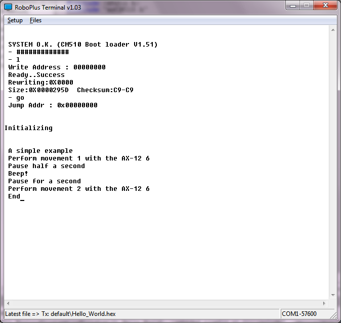
If you have installed the necessary software (WinAVR must be installed in "C:tools WinAVR-20100110") and unzip this zip file in the root directory (C: ) you have to be ready to modify, compile, or simply load the executable "hello_world.hex" in the CM-510. You will see something similar to:

[caption id="attachment_584" align="aligncenter" width="300"]01_Hello_World_CM-510 01_Hello_World_CM-510[/caption]

Some explanations
dxl_write_word (ax12Id, P_GOAL_POSITION_L, 600);

This function is included in the Robotis CM-510 libraries allowing us to send commands to a Dynamixel actuator very easily. We only have to indicate the ID of the AX-12 to move (ax12Id), the code of the order that the AX-12 should execute, in this case go to the goal position (P_GOAL_POSITION_L), and the position in which has to be placed between 0 and 1024 (600 in the example).

dx_series_goal


Highlights:

Decompose the program into different parts

  •     Having previously created the init () function in myCM510.h/myCM510.c allows us to include it easily in this program.

  •     In addition to simplifying programming we can reuse the same code in different programs. This saves us from having to repeat the same code many times and, especially, have to correct faults or improve in only one point, . Later we will see how to organize directories and even how to create libraries.

  •     It also allows us to encapsulate the details, so that when the program starts growing we can handle them easily without being overwhelmed.


Showing what is doing running the program


Using the printf function we can send text to the screen that lets us know what is doing the program (printf sends to the serial port, "RoboPlus Terminal" read it  and displays it on the screen. We will lear how to read from the serial port when we start programming Bioloid using a PC or SBC)

Can you think of an easy way to avoid having two similar functions such as "void executeMovement1 (int ax12Id)" and "void executeMovement2 (int ax12Id)"?

lunes, 9 de abril de 2012

Learning scurves with AX-12

I'm learning how to use scurves with AX-12, so I've created a test CM-510 C program where I try different approachs. Any help will be very well received, because my goal is to control several AX-12 and I'm far far away from it!

Here is the program with an spreadsheet with the calculations (LibreOffice and Excel). I have started from an old post from Bullit in the Tribotix forum (now in PDF format at Robosavvy)

Clockwise is the standard motion, counter clockwise is the scurve intended motion

[youtube http://www.youtube.com/watch?v=YBdO0232QvQ]

jueves, 16 de febrero de 2012

Programming Lego Mindstorms NXT

Lego Mindstorms NXT is a great kit that allow you to build and program an almost unlimited variety of robots and automatisms.

NXT brick

Mindstorms NXT

The kit includes a "brick" that includes a programmable 32 bits microcontroller. Lego open sourced the software and the hardware of NXT, here you can find all the documents and source code.

You can program its microcontroller with the included visual programming tool, called NXT-G, that is very easy to use for small programs but probably you will find it too much limited, specially if you can program in other programming language. But don't worry, you can use standard and professional programming languages like Java, C or C++ among others. All them free as in beer and as in speech.

Just a few words about which, in my opinion, are the best options:

C like language: NXC

Apart from NXT-G the easiest way for programming NXT is NXC. It's a language similar to C, very easy to learn and you don't should change the NXT Lego firmware, so you can continue using NXT-G.

Java: Lejos

If you know or want to learn Java this is your tool. I think that is the best tool, more difficult that NXC but far more powerful.

C/C++: NXT OSEK

Do you want to learn C or C++? Real time programming? This is your tool!

martes, 7 de febrero de 2012

Choose hardware, firmware and language

There are a lot of possible combinations of hardware, firmware and languages for programming Bioloid. I think that the table below show the the main combinations.

You can choose from the easy but limited Robotis own tool (Roboplus Task) and only your CM-5 or CM-510 to a SBC or "embedded" PC like Roboard and any language which can manage a serial port connection, like C, C++, Java, Python,...

Linux C++ Dynamixel reading and writing example

C# Dynamixel reading and writing example

Practical C++ programming tutorial for Bioloid

[caption id="attachment_256" align="aligncenter" width="617"]Programming Bioloid: choose hardware, firmware and languages Programming Bioloid: choose hardware, firmware and languages[/caption]

Robotis officially supports the programming solutions with the blue background:

  • The dark blue, RoboPlus Tasks, is the only one in which you can create the motions with RoboPlus Motion and execute it in CM-5/CM-510 with the program create with RoboPlus Tasks, after downloading the generated executable into the CM-5/CM-510, of course.


With these programming solutions you can use the Zigbee SDK to send and receive data between the CM5-/CM-510 and any computer, using Zig-110A or the new bluetooth BT-110, the Zig2Serial and the USB2Dynamixel. You can download example in Visual Basic .Net, C# and Visual C++

But there are more options!

Using a PC, SBC (Single Board Computer), PDA, Mobile or other light and battery powered computer

Using a serial port connection with your more beloved programming language:

  • USB2Dynamixel


If you have any device with a USB host and a FTDI driver you can use USB2Dynamixel to command programatically your Dynamixel servos using the Dynamixel protocol. You only will need your CM-5 or CM-510 to connect your Dynamixel to the battery.

  • Serial port cable


Same as the previous option but instead of using the USB2Dynamixel you only will need the serial cable and the "Toss Mode" launched with the 't' command from the "Manage Mode"


  • Wireless control


Instead of only sending and receiving data, with the previous wireless connections you can command remotely your robot using the standard firmware and the "Toss Mode" launched with the 't' command from the "Manage Mode". You will need to command it using the Dynamixel protocol.

With these options and the CM-510 you will find a little problem... there is no way to read your sensor values! Well, you can use this firmware that offers a "Toss Mode" that supports reading CM-510 ports.

Start learning!

If you want to start learning how to program your CM-5 or CM-510 controller you will find interesting this post "Start programming  CM-5/CM-510 in C". But may be you prefer to control your robot from a PC, SBC or other computer in C++ or C#

martes, 22 de noviembre de 2011

CM-5: Creating a simple "Hello World" C program

This post try to explain how to compile, load in the CM-5 (transmit) and execute a C program (a servo version of the "Hello World" classic example).

What do you need?


(You can find here how to start programming CM-5 / CM-510)

Obviously, some Bioloid hardware:


- The CM-5


- The battery or power source


- The serial cable


- An AX-12


- A cable to connect the AX-12 with the ID 17 to the CM-5. You can change the ID in the program.


What should you do?


1. Download and install the software:


1.- Download and install the Robotis RoboPlus software.


2.- Download and install WinAVR


3.- Download a Hello World example for WinAVR.


The C “Hello World” servo program is based in the original Robotis example.


4.- You should create a folder for your CM-5 program, for example c:myprojectscm5helloworld Copy there the previously downloaded helloworld.zip and unzip it.


2. Compile and link the program


1. Execute WinAVR and open the unzipped project:


( Bioloid User's Guide.pdf could help you using WinAVR)


You should change the ID 17 of the servo for the ID of the servo you are using


2.- Compile and link. Make all:


3.- You should see “Errors: none”


4.- Transmit and execute the helloworld.hex to the CM-5


( Here you can find more info )


Well, if you only want to test the executable, you can download only the hex.


When loaded you should see an screen with two equal values as a correct "Checksum" check (in this example the value is 81, it's calculated from the source code). If the values are not equal there is an error in the transmission.


CM5HexLoaded


5.- Every time you press the red MODE button the servo should spin